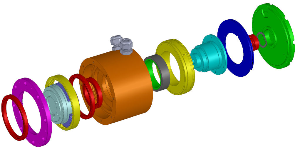
When most engineers think of a brushless DC servo motor, they’re likely to visualize a housing with a flange to accept mounting bolts, connectors to accept power and data cables, and a rotor shaft that couples to the load.
Hidden inside, they imagine a stator consisting of a stack of slotted laminations filled by copper windings. Within the stator is a rotor with permanent magnets that interact with the stator’s electromagnetic field to produce rotary motion. The permanent magnet rotor is mounted to a shaft supported by bearings at both ends that allow it to turn freely. A feedback device may also be incorporated into the design.
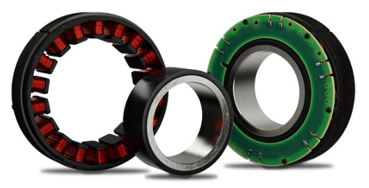
That’s the most common servo motor design, but what if you eliminated everything except for the rotor and stator — no housing, no shaft, no connectors, no bearings, no integrated feedback?
That’s the bare-bones design of a frameless servo motor — a design that offers many advantages and opportunities for certain types of applications. Let’s look at why you might choose a frameless motor and how to integrate it into your machine.
Why Frameless?
With no housing, bearings or other components beyond the stator and rotor, a frameless motor delivers the most compact, torque-dense motion possible. Instead of its own housing, the motor can be embedded directly within the mechanical design of the machine. Instead of its own bearings, it can use the machine’s existing shaft and bearings.
For these reasons, frameless servo motors can be an ideal choice for compact, higher-level assemblies — for example, rotary actuators — where the design goal is to achieve the highest torque and precision in the most compact form factor.
Embedded directly into the machine, frameless motors can also be protected from harsh environmental conditions, such as those encountered in high-pressure washdown or submersible applications. With frameless motors, machines can be lighter, more compact and more precise while requiring less maintenance.
How to Integrate a Frameless Motor Into Your Design
All of that said, embedding a frameless motor does require more attention to design details compared to bolting on a housed motor and coupling it to the load or a gearset. Here is a top-level view of the most important design considerations.
First, determine the components you need to complete the frameless motor-based mechanical system:
- Gearing. Frameless motors are often used to drive the load directly, with no backlash, compliance or lost motion. If a gear system is needed to increase torque, appropriate choices include compact spur, planetary, cycloidal or harmonic (strain wave) gearsets. Harmonic gearing is particularly attractive for applications that require a high reduction ratio in the most compact form factor with zero backlash.
- Feedback device. Most often, you will want to use an encoder (incremental or absolute, depending on the application). In the most rugged environments, a resolver could possibly be the preferred choice. These feedback devices detect rotor position to enable closed-loop velocity and position control. Hall tracks on an encoder or a dedicated Hall effect sensor built into the motor provides information the servo drive requires to properly commutate the power delivered to the motor.
- Brakes. Electromagnetic or mechanical brakes may be required to provide holding torque and to ensure safety (especially in vertical applications) in the event of a power outage or other system failure. A brake may also be used to “park” a load in a stable position when the motor is powered down.
- Bearings. The frameless rotor is coupled directly to the machine axis’s own rotating shaft, supported by its own bearings. There’s no need to change the overall machine design, but you do need to understand where the shaft and bearings are and determine a point on the shaft where the rotor can be added, then build the housing element for the stator based on this position.
Next, consider other machine design elements:
- Form factor. Is your mechanical design constrained in terms of motor diameter or length? Frameless motors are available in both torquer (shorter axial length) and servo (longer axial length) designs. If your application can accommodate a relatively compact axial length, note that the larger diameter of a torquer design allows you to take advantage of the D2L rule to achieve maximum torque density.
- Heat dissipation. Since the frameless stator is embedded directly into the machine, make sure the housing material that supports the stator provides adequate heatsinking. Typically, there needs to be at least 4–6 mm of wall thickness in the immediate vicinity of the stator. Aluminum is the best and most commonly used thermally conductive material for this purpose. Steel is also good, although some stainless steel alloys may be less effective at drawing heat away, and their use should be conditioned on appropriate design review.
- Understand thermal limitations. Consider the effects of heat within the mechanical system based on how the motor fits into the assembly. For example, how will a motor rated at 155°C maximum winding temperature affect lubricants and electronic components in the tight confines of a rotary actuator?
Even with effective heatsinking, the temperature within an inch or two of the motor armature may be only 15°C to 20°C lower. Ensure that heat-sensitive components are placed far enough away and/or consider a motor capable of delivering the required torque and speed at a reduced maximum winding temperature. Design tools available on the Kollmorgen website allow design engineers to see how our frameless motors perform at the thermal limits required for the application. - Consider thermal sensors. These can be used to determine whether the motor gets too hot. A PTC (positive temperature coefficient) thermal device added to the servo drive can ensure that the system safely shuts down if necessary. During prototyping, you may want to use a linear thermistor sensor to gauge how hot the motor gets when running at its required torque/speed load point. In advanced control systems, sensors can be used to monitor when the motor is driving too hard and help the system decide when maintenance is needed.
- Design for manufacturability. When designing a motion system such as a rotary actuator, begin with the end result in mind, including all the steps and costs that will be involved in manufacturing the device as well as maintaining it over its lifetime. Remember that building a prototype is not the same as full-scale manufacturing. Make sure you have a reliable source for all components and that the assembly process is straightforward.
Also be aware of the high magnetic forces present in the permanent-magnet rotor. Plan for any specialized tooling and fixtures you will need to assemble motors safely.

Why Use TBM2G Frameles Servo Motors?
Kollmorgen offers a full range of frameless servo motors in our proven TBM and KBM series as well as our innovative TBM2G series. From 24 to 680 VDC bus voltages, from high-torque to high-speed application requirements, from ordinary to harsh and extreme environments — there’s a Kollmorgen solution for nearly every application that benefits from frameless servo technology.
The TBM2G Series, our newest and most innovative motor family, uses a torquer (pancake) design to provide the highest torque density in an extremely compact electromagnetics package. If the torquer form factor suits your application requirements, here are the top reasons to choose TBM2G:
- Thermal efficiency. Compared to the 155°C maximum winding temperature of competing motors, TBM2G motors are optimized to perform exceptionally well at a winding temperature of only 85°C (although they can also sustain even higher continuous performance at the 155°C maximum winding temperature).
The low thermal rise of TBM2G makes it ideal for use in tightly confined spaces, where higher temperatures could otherwise damage bearing and gear lubricants, feedback electronics, and other heat-sensitive components. - Broad range of sizes. Optimized for voltage buses up to 48 VDC, TBM2G motors are available in seven frame size diameters (50–115 mm), each with a choice of three stack lengths (8, 13, 26 mm) and three winding variations (A, C, D). That’s a total of 63 standard configurations to fit practically any low-voltage application.
- Ready to scale. Kollmorgen can deliver prototype motors as fast or faster than our competitors while maintaining the highest quality. Even more important, once your design is finalized, we can rapidly scale up to full production quantities — while maintaining perfect consistency — to help you bring your machine to market faster, with confidence.
As a Gold Partner, Micromech are able to supply and provide expertise on Kollmorgen products. Contact our sales team on 01376 333333 or sales@micromech.co.uk for price and delivery or technical assistance.
